A little space. A better plan.

Make room for
what’s underneath.

Explore the connections that fit Nebula’s rear panel, then see how their wiring and your equipment share the space underneath.

01 / Connection options

Choose the connection your rig needs.

These Neutrik examples use the round D-pattern mounting positions on Nebula’s rear panel. Choose a family, then an internal connection. Compare the space it needs and take the exact Neutrik reference to your usual shop.

Solder short internal wires to the terminals. This example adds 16 mm for the local wiring bend.

Behind the panel

Jack · space to reserve

Rear hardware + room to connect it.
Dimensions in mm · example cable allowances

A

What sits behind the panel

Side view · from the mounting face

Soldered jack: 29 mm socket and terminals plus 16 mm of wiring space The rear panel is on the left. The socket extends into the board on the right. A dashed amber box includes the socket and short internal wiring, totalling 45 mm. OUTSIDEINSIDE NEBULA 1 2 45 mm Rear panel
1 Socket + terminals29 mm
2 Short wiring16 mm
Reserve depth45 mm
B

The space to keep clear

Detail · seen from underneath

A reserved footprint 28 mm wide and 45 mm deep A shaded rectangle extends inward from the rear edge. Keep pedals and other equipment outside this socket zone. REAR EDGE 28 mm 45 mm AMBER AREA = KEEP CLEAR

Start with a 28 × 45 mm clear zone (width × depth).

Width and depth are planning allowances. Downward or sideways plugs also need clearance in that direction.

In the Builder, choose Jack → Soldered · short wiring. Its preset fills in this clearance automatically. The socket reaches 29 mm behind the mounting face; the preset adds 16 mm for short wiring.

Wiring / plug space is an example allowance, not a manufacturer dimension or minimum bend radius. Check the actual cable and plug, including sideways or downward projection. Drawing depth uses the same scale within each family. This guide does not change your Builder layout.

Compare connection styles & references All five families · width × depth
Each row is a connection arrangement. Repeated product references mean the cable or wiring changes; the socket stays the same. Hardware values marked ≈ are rounded estimates. Added space and clear zones are planning allowances.
ConnectionNeutrik referenceRear hardwareAdded spaceClear zone
W × D
JackSoldered · short wiringNJ3FP6C ↗29 mm16 mm28 × 45 mm
JackSoldered · roomier wiringNJ3FP6C ↗29 mm26 mm28 × 55 mm
XLRCompact solderedNC3FD-L-1 ↗≈ 22 mm13 mm28 × 35 mm
XLRStandard solderedNC3FD-LX ↗≈ 25 mm20 mm28 × 45 mm
XLRPlug-through · straightNA3FDM ↗≈ 52 mm88 mm36 × 140 mm
USB-CFixed leadNAUSBC-5G-FL10 / NAUSBC-5G-FL15 / NAUSBC-5G-FL20 / NAUSBC-5G-FL25 ↗≈ 44 mm21 mm36 × 65 mm
USB-A/BUSB 2 · angled plugNAUSB-W ↗≈ 36 mm24 mm36 × 60 mm
USB-A/BUSB 2 · straight plugNAUSB-W ↗≈ 36 mm44 mm36 × 80 mm
USB-A/BUSB 3 · angled plugNAUSB3 ↗≈ 40 mm25 mm36 × 65 mm
USB-A/BUSB 3 · straight plugNAUSB3 ↗≈ 40 mm50 mm36 × 90 mm
EthernetPunch-down wiringNE8FDV-YK ↗≈ 42 mm18 mm36 × 60 mm
EthernetPlug-through · downwardNE8FDP-R ↗≈ 32 mm8 mm36 × 40 mm
EthernetPlug-through · straightNE8FDP ↗≈ 35 mm40 mm36 × 75 mm

On a small screen, swipe across the table to see every column. The downward Ethernet option also needs space below the socket for its cable plug.

These models share Nebula’s nominal 24 mm round opening and 19 × 24 mm screw pattern. The figures above concern space inside the board; the separate rectangular IEC opening takes its own matching inlet.

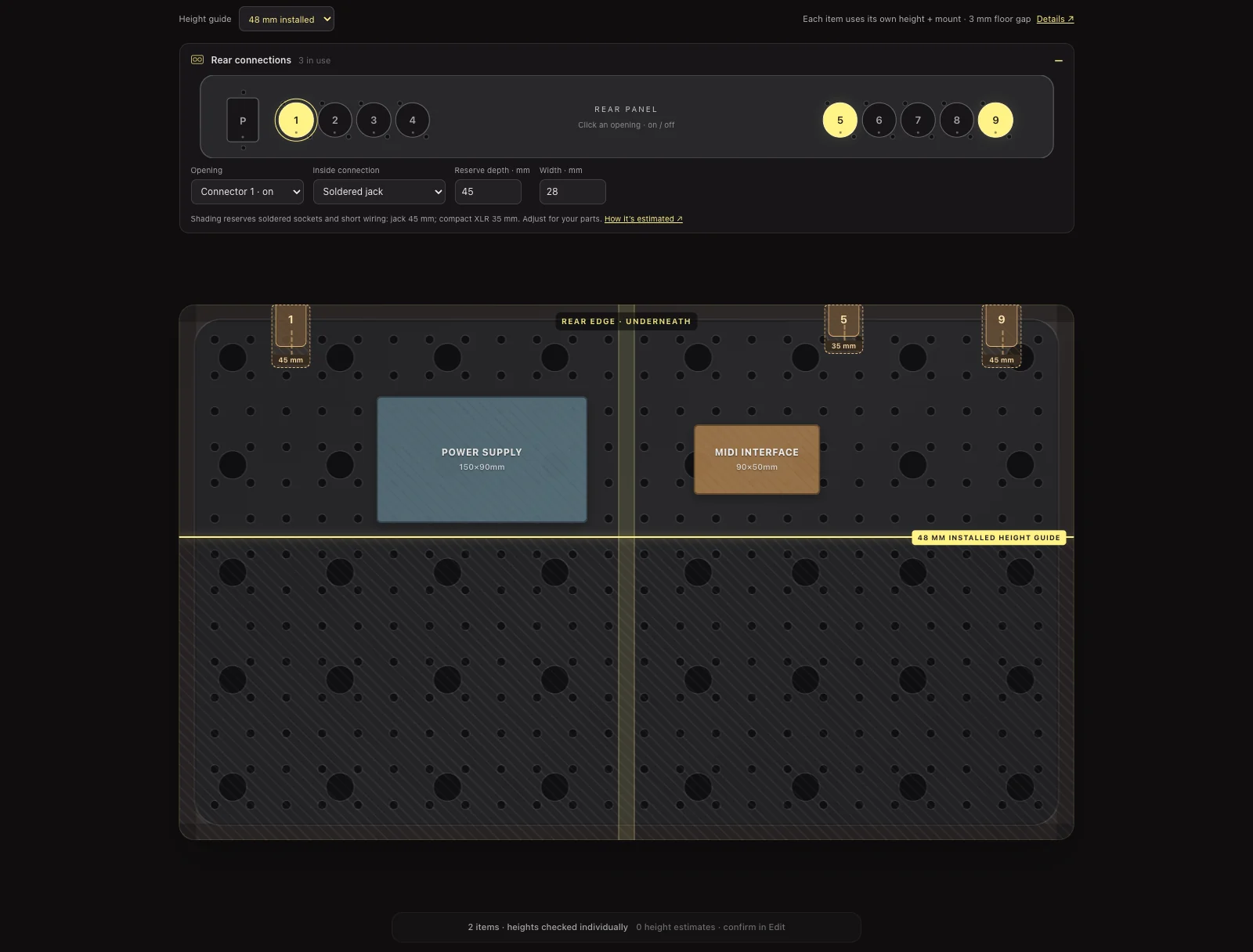
Actual Builder view with rear openings 1, 5 and 9 enabled and amber socket zones on the underside
In the Builder: three openings enabled. View larger ↗ (opens in a new tab)

Putting it on your board

Switch on a socket.
See where it reaches.

  1. Choose an opening. In Under, open Rear connections and click the opening you plan to use.
  2. Set its allowance. Choose the matching connection preset to fill in its clearance. Adjust only if your chosen hardware or cable arrangement needs different space.
  3. Arrange around it. Shaded zones stay clear when placing equipment. Existing overlaps are highlighted; move the item or use Optimize. Locked items stay put.

02 / Underside height

Lower equipment can sit farther forward.

Nebula’s sloping deck leaves more room at the rear. The Builder checks each item’s height plus its mounting thickness, with a 3 mm gap to the floor.

C

Follow the slope

Side section · rear on the left

48 mm installed height leaves a frontmost edge of 164 mm from the rearThe deck slopes down towards the front. The yellow line marks the frontmost edge for this installed height. The floor gap is included in the calculation. REARFRONT FLOOR 164 mm 3 mm floor gap
Mount Item height Frontmost edge

Height envelope shown. Each item’s full footprint must fit before its own yellow line.

Installed height48 mm

Item + mount

Frontmost edge from the rear164 mm

The whole item must sit within this depth.

The Builder’s yellow line is a guide for the selected installed height. Dragging an item updates it to that item’s height. Shorter items can fit beyond another item’s line because each is checked independently. Rear sockets and structural obstructions can reduce the available space further.

03 / Dimensions & sources

Starting points, with room to adjust.

Use the presets to plan, then check the dimensions of your chosen equipment and connectors.

Behind the rear panel

The selected product links to its Neutrik page and drawing. Clearances use front mounting and measure rear hardware from the mounting face. Product references identify the shown connector; finish, gender and cable type matter when ordering.

How each hardware depth was established

NJ3FP6C drawing ↗: 29 mm behind the mounting face, including terminals, from the manufacturer drawing.

NC3FD-L-1 drawing ↗: 16.3 mm rear body plus projecting terminals; approximately 22 mm is allowed for the assembly.

NC3FD-LX drawing ↗: 24.1 mm including terminals in the drawing, rounded up to 25 mm for planning.

NA3FDM drawing ↗: Approximately 51.5 mm behind the mounting flange in the manufacturer model, rounded up to 52 mm.

NAUSBC-5G-FL10 / 15 / 20 / 25 drawing ↗: Approximately 43.3 mm from the flange to the end of the boot, rounded up to 44 mm. All four lead lengths use the same local clearance.

NAUSB-W drawing ↗: 40.5 mm overall minus 5 mm ahead of the mounting face gives 35.5 mm inside, rounded up to 36 mm.

NAUSB3 drawing ↗: 44.5 mm overall minus 5 mm ahead of the mounting face gives 39.5 mm inside, rounded up to 40 mm. The separate 29 mm drawing dimension excludes the projecting rear socket.

NE8FDV-YK drawing ↗: 28.3 mm to the terminal block; the clamp reaches approximately 41.5 mm in the manufacturer model. We allow 42 mm for both.

NE8FDP-R drawing ↗: 31.7 mm behind the mounting face for the front-flange arrangement shown, rounded up to 32 mm. Plug and cable also project downward.

NE8FDP drawing ↗: 34.55 mm behind the mounting face for the front-flange arrangement shown, rounded up to 35 mm.

Model-derived measurements use the official NA3FDM model, USB-C model and NE8FDV-YK model.

Below the deck

The board model provides about 90 mm from the wood’s underside to the floor plane at the rear, tapering to approximately zero at the front. The guide uses the same slope and 380 mm deck depth as the Builder.

Example heights are based on CIOKS DC7, Strymon Zuma R300, Strymon Zuma and Boss TU-3. Other library items start with a marked 45 mm estimate. The examples here use a 3 mm mount. The DC7’s quoted height excludes its rubber feet; include any feet you retain in your measurements.

For example, a 59 mm-high item has a frontmost edge of 105 mm with a 3 mm mount. If its depth is 129 mm, it needs a shorter orientation to fit within that limit.

What the guide allows for

Clear zones cover the selected rear hardware and an example of compact internal wiring. Added cable / plug space and widths are planning allowances, not manufacturer specifications. Cable bend requirements vary with the cable you choose. Keep the remaining cable run and its device-end plug clear too. Height uses rectangular item envelopes, the board’s slope and a 3 mm floor gap. Knobs, added feet, cables and mounting thickness must be included in your own measurements. The longer plug-through examples include a planning allowance for a rear plug and bend. They are not a guarantee of fit for every cable assembly. Angled connections can exchange depth for sideways or downward space.